Piper Archer II Structural Analysis
I worked with a team to write a 50 page report analyzing the structural integrity of the Piper Archer II aircraft under 3 different load scenarios: maximum climb, critical loading, and landed. Aerodynamic loads, inertial forces, and operational stresses throughout the plane's lifetime were investigated- separately on the plane wings, fuselage, and empennage.
I was responsible for completing the fuselage free body diagrams for each load case. I designed COMSOL simulations to calculate the aerodynamic loads (lift and drag) and center of pressure of the fuselage, and used assumptions to calculate the center of gravity of the fuselage. I also created shear force and bending moment diagrams for the fuselage stress analysis.
I was additionally responsible for determining the bending stress and shear flows across a cross-section of the fuselage. I simplified the geometry of the fuselage to a 16 boom-and-panel structure, referencing the airplane parts catalog and engineering drawings of a stiffener similar to the one used for Piper Archer II. I designed a code in MATLAB that could be adapted to all 3 load scenarios, which necessitated an input of bending moment and shear force and output a bending stress and shear flow value at each boom/panel. I modeled the cross-section of the fuselage in SolidWorks and performed finite element analysis to visualize bending stress concentrations in the skin and stiffeners.
Main MATLAB Skills Used
-
Numerical modeling of thin-walled structures, implementing algorithms from theory
-
Data structures and tables
-
Performing operations on vectors
Work is on page 16-22, 33-36
Fuselage Free Body Diagrams
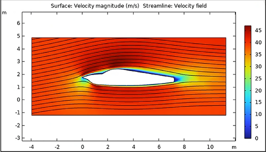
Velocity Field Surrounding Fuselage (Max Climb):
Contour Plot of Pressure on Fuselage Surface (Max Climb):

FBD of Y-Z Cross Section of Fuselage (Max Climb):

FBD of X-Z Cross Section of Fuselage (Max Climb):

X-axis SF and BM Diagram of Fuselage (Max Climb):

Fuselage Shear Force and Bending Stress Analysis
Idealized Fuselage Cross Section Drawing:


Fuselage Bending Stress Concentration Plot:
